Hardware Support: NAC Services RPS
Please note that JMRI's RPS support is being rapidly improved. This page refers to
most recent JMRI test version. If you're using an RPS system, you should update to new test
versions as they are announced.
The RPS System allows
you to locate the exact position of locomotives and other rolling stock that have been
equipped with transmitter decoders. The system makes up to 10 measurements per second and
each reading is accurate to much better than an inch, which makes many imaginative uses
possible.
Supported Hardware
DCC Systems
The RPS system works in conjunction which your DCC system to control when the RPS
transmitters are activated. You therefore need a working connection between your DCC system
and JMRI to use RPS.
At the present time, RPS is supported with DCC systems from:
Others may work, and we're interested in making them work, but they haven't been tested in
combination with RPS yet.
Connecting
First, get your DCC system working and connected to JMRI. As a good test of the
connection, you should be able to turn your layout power on and off from the JMRI Power
Control in the Tools menu.
Wiring
Next set up the RPS hardware following the RPS instructions. You may want to only install
a few (but a minimum of three) receivers while you're first getting the system working.
Next, connect your computer to the RPS using either a USB connection or an RS232 cable
from a serial port. If you use an RS232 cable, note that it should be a "straight-through" or
"modem" cable, not a "crossover" or "null-modem" cable.
Settings

To configure RPS in JMRI:
- Start your JMRI-based program: DecoderPro, PanelPro, etc.
- Go to the Connections tab of the JMRI Preferences. This opens automatically the first
time the application is run, or you can select it from the "Edit" menu.
- Your DCC connection should already be configured in the top section, as you tested it
three steps back.
- Click on the "+" sign to the right of your current Connection to open a new Connections
pane.
- Select "NAC Services" from the list as the "System Manufacturer".
- Select "RPS Base Station" as the "System Connection".
- In the associated port selection box under Settings, pick the name of the serial port
that you have connected to the RPS system.
- The baud rate will show a fixed value of 115,200 baud.
- As a temporary measure during development of the system, there's a "Protocol" option to
select.
The valid choices are "Version 1" and "Version 2"; your hardware determines which to use.
Most current RPS systems use "Version 2". This selection will eventually be
automated.
- Click "Save". You'll be asked if it's OK for the program to quit, click "Yes".
- Restart the program. It should come up saying it's connected to your DCC system, and
just below that saying it's connected to the RPS Base Station on the proper port.
- Next, you have to enter alignment information. From the RPS menu, select "Receiver Control".
This will open a new window.
- In the middle of that window, enter the number of highest-numbered receiver you've got.
For example, if you have three receivers numbered 2, 3 and 6, enter 6 in the field.
Press the "Set" button next to that field.
- In the table at the top, enter the X, Y and Z position of each of your receivers. If
you don't have a receiver with a particular number, leave that row blank. For now, just
enter approximate values.
- Check the boxes next to each receiver you have hooked up, and make sure that there's no
box checked next for receiver numbers that are not yet connected.
- Click the "Set Defaults" button to save these positions as default values. They'll
appear again when you next start the program.
At this point, your RPS system is ready to go.
To have your RPS system start measuring positions, you have to tell it to poll the
Locomotives in which you've installed RPS transmitters.
To do this:
- Open "RPS
Polling Control" from the RPS menu
- You should see all of the Locomotives in your Roster
- Check the box under "Poll" for each Locomotive in which an RPS Transmitter is
installed
- Check the "poll" box to start making measurements
- Click "Store New Default Values" to store these settings so they'll be used the next
time you start JMRI.
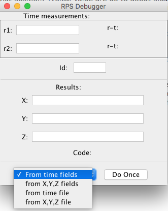
To see that the system is working, open the "Debugger Window"
from the RPS menu. You should see time readings coming in and being converted to positions.
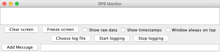
You can also check the communications with the unit by opening the "RPS Monitor" from the RPS
menu.

JMRI provides a number of tools in the RPS menu for working with an RPS system:
- RPS Monitor
-
The pane displays all traffic seen on the connection
-
Receiver
Control
-
This is where you enter position information about your receiver positions, etc.
-
Polling
Control
-
This is where you tell JMRI which locomotives have RPS transmitters, and how often you
want JMRI to poll them.
 Older Polling Control pane
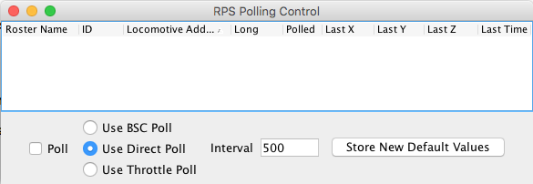 Version 4.1.6 Polling Control
pane with new options
Version 4.1.6 Polling Control
pane with new options
-
Debugger
Window
-
This tool shows you the readings and measurements as the system makes them.
-
Tracking
Display
-
This tool shows the points as they are measured on a graphical display.

-
Sound Speed
Monitor
-
This tool lets you see and set the speed of sound used by the RPS system, and can set it
automatically in certain cases.

-
RPS
Alignment
-
This tool lets you read and calculate spatial coordinates.

You can also display RPS information on PanelPro Control Panels using an "
RPS Icon".
RPS information may be used to detect occupancy using JMRI RPS
Sensors.
Documentation
Third Party info
More information on the RPS Web Site.